Skip navigation

Category Archives: instrument repair

This guitar, a Recording King Tricone Resonator, came into the workshop with a problem.  It’s owner, guitar virtuoso Roland Chadwick, wanted to use an open C# tuning  (C#,G#, C#, F, G#, C#) but couldn’t get it to play in tune. A web search rapidly revealed that these guitars are notorious for giving trouble with open tunings. There are probably several reasons including the high action at the nut and coupling of certain notes with strong body resonances, but another cause seems to be too little compensation at the bridge.  With an open C# tuning, this results in the two lower strings sounding more than 20 cents sharp at the 12th fret.


At one time, a replacement bridge was made which allowed the compensation of each string to be individually adjusted. (You can see it here.)  It looks an excellent design but unfortunately, it’s no longer obtainable. What to do instead?

I decided to follow a similar route but to get there by modifying the existing bridge rather than  making a new one.  I simply glued small pieces of ebony onto it and reshaped the string slots  to provide a few millimetres of compensation for the 2nd, 5th and 6th strings. I say simply but, although the idea is straightforward, it’s a bit tricky in practice because the shape of the bridge and existing saddle makes it hard to clamp the small lumps of ebony in place while the glue cures. I solved the problem by making a cast of the opposite side of the bridge from car body filler – a technique that I’ve described in detail in the Tools and Jigs section of this website.

Below are a few photographs of the modified bridge and the guitar with its top off while final adjustments were being made.


I didn’t succeed in getting it to play perfectly in tune over the whole length of the fingerboard, but the intonation is a lot better and I think that Roland will now be able to play it without making his audience’s ears bleed.

Advertisement

Most vices won’t let you file a nut or saddle to shape. Their jaws are too wide and get in the way. Stew Mac make a special vice with tall narrow jaws to get around the problem. I haven’t tried it but I should think that it works fine.  However, it’s quite unnecessary. A simple pair of wooden jaws does the job perfectly well.


The jaws in the photographs below were intended as a prototype. I was planning to make a pair of jaws out of gauge plate or aluminium sheet and wanted to check that I’d got the size about right and that the idea was feasible. It turned out that the wooden version worked so well that I didn’t need to bother.


As I hope can be seen in the photographs, the device is little more than a couple of pieces of maple about 5mm thick, hinged together at their lower ends with glass fibre reinforced tape.


This charming little guitar came into the workshop recently. The tightly arched back had come away from the linings in a couple of places at the edges of the upper bout and needed re-gluing. I also made a new saddle to replace the existing poorly-fitting piece of plastic and fitted a set of new strings. Otherwise, the guitar was in remarkably good condition for its age.

 
p1060324-edit
 

The label inside the guitar attributes it to Adolf Kessler junior of Markneukirchen, where it was probably made in the last part of the 19th century.

The Musical Instrument Museum in Markneukirchen has an on-line forum where I discovered that Adolf Kessler had founded a mail order business there in 1886, selling guitars and violins. I guess Kessler was a business man who marketed instruments made by some of the many craftsmen working in the town at the time. There’s a short BBC film about Markneukirchen and its 400 year history as a centre of musical instrument manufacture here.

 
p1060332
 

The rosette is made from decorative shapes of mother of pearl set into mastic.

 
p1060336
 

The ribs and back are of plain wood, perhaps maple, with a painted faux grain pattern under the varnish.

 
p1060329
 

The ebonised bridge is neatly carved into fleurs de lys at the ends, although the bass side has sustained some damage.

 
p1060335
 

The headstock carries Stauffer style tuning machines.

 
p1060326
 

Altogether an attractive little instrument – and I’m pleased to think that it is ready to make music again.

Among the treasure trove of information and tips and tricks at Frank Ford’s website Frets.com there’s a description of how to turn a single-edge razor blade into a miniature cabinet scraper for repairs of guitar finishes. Click here to read it.
 

DSC_7599


I thought that this was a really clever idea and immediately ordered a box of blades to try it out. Ford says that he draws the edge of the blade across a round piece of hard steel such as a screwdriver shank to create a fine hook just as one might finish a full size cabinet scraper.

I’m not sure why, but I couldn’t make it work. Maybe it was my technique or perhaps the steel of the blade had hardened during the sharpening process but despite repeated trials all I could produce was a ragged edge that scraped less well than a blade straight from the box.


The solution was first to grind off the bevelled edge of the blade;


DSC_7600


then to make the blade edge straight and square on a diamond stone;


DSC_7603


and finally to turn a hook with a burnisher in the usual way.


DSC_7606


These little scrapers work extremely well if you need to remove polish or varnish and they’re easy to re-sharpen.


DSC_7598

I’ve been a fan of Roland Chadwick’s music since hearing a performance of his trio for classical guitar, Letter from LA, a few years ago. So I was delighted when he contacted me about a guitar that needed some attention.

It was a fine instrument too – a cedar top classical guitar made by an Australian guitar maker, Simon Marty, in 1988. Quite apart from being 25 years old, it had worked hard for its living and the thin cedar top had developed some nasty cracks in the widest part of the lower bout. Some of the internal braces had come unglued too, and the guitar was more or less unplayable. To make matters worse, someone had tried to repair the cracks with superglue.

This is what it looked like after I had scraped away most of the superglue.

DSC_6804

With a hand through the soundhole, I could feel that the cracked part of the soundboard had become detached from a long transverse bar running across the instrument under the bridge. This explained the multiple little dowels, which were a previous attempt to fix the problem. The only thing to do was cut out the damaged wood and replace it.

DSC_6822

I also needed to replace some missing braces and re-glue several that were beginning to come unstuck. The difficulty here was that the braces, constructed out of balsa wood and carbon fibre, were very thin and it was almost impossible to position conventional clamps accurately enough to hold them in place without distortion. In the end, I solved the problem by making a few spring-loaded miniature go-bars. Wedged between the back of the guitar and the top of the brace, they kept everything in place while the glue cured.

DSC_6955

DSC_6957


After re-polishing, it was ready to perform again. All well worth the trouble because, despite its age, it’s an excellent guitar which produces a big warm sound.


DSC_6834

When working on the top of a guitar, I put the instrument on a carpet covered bench and prop up the neck on a block of wood that has a shallow, foam-lined curve cut into the top – as you can see in the photograph above. But I’ve recently learnt a better method. The device below, made out of 2 semi-circles of 18mm plywood, radius about 3 inches, adjusts itself automatically to the taper of the neck and supports it in a far more stable way.

The danger when using the simple block is that it tips over if the instrument is moved along its longitudinal axis. Of course, one can always clamp the block, but with the new neck cradle there’s no need. I’m grateful to Richard Nice (who invented the plane that I wrote about in my last post) for this bright idea.

A while ago, I wrote about repairing the damaged soundboard of a cedar topped guitar. And I’ve recently had to deal with a similar problem, this time caused by the lid of the case falling on the guitar as it was being lifted out. The damage wasn’t structural but it did leave some conspicuous dents.

The soundboard had been finished by French polishing and I reckoned that simply re-polishing the damaged area would be almost enough. However, first, using a hot (but not too hot) iron and some wet kitchen paper, I steamed out the dents. When dry, I lightly sanded the area before brushing several coats of clear shellac into the places where the polish had been chipped off. After a couple of days to allow it harden, I sanded again with 1500 grit paper to level the area and then re-polished the whole of the lower part of the soundboard in the traditional way using a pad to apply the shellac. Another few days for the shellac to harden, a quick buff up with some burnishing cream and damaged area was almost invisible.

But not completely invisible because, viewed in certain lights, the repaired areas were just identifiable as slightly paler patches. You can see them in the photograph below. I had exactly the same problem with the last repair and I don’t know how to eliminate it. This time I tried exposing the bare wood to UV light for a few hours before applying any shellac but I’m very doubful that it made any difference. Maybe I should have left it under the UV light for longer. If anyone has a better idea, I’d love to hear from them.

My cello is making progress, even if rather slowly. I’ve just closed up the box, which is a step that requires a lot of clamps to hold everything in position while the glue sets.


And here’s the problem: where to find enough clamps. One solution is to buy or, cheaper, make spool clamps for the job. But these clamps are less than perfect because the force they exert operates at the edge of the plates rather than directly over the ribs. For clamps that put pressure in the right place, you have to buy a set of the dedicated cello clamps made by Herdim®, which, I’m told, are easy to use and work well. Unfortunately each of the Herdim® clamps costs about 15 Euros, so getting equipped with the 40 or so that are needed for a cello is quite expensive.

Partly out of meanness and partly because I enjoy making my own tools and jigs, I devised this alternative. The photographs make it fairly clear how the clamps are constructed and instructions are probably unnecessary. But perhaps a few details will be helpful. The clamping force is supplied by a wing-nut on 6mm studding. I made at least half of the clamping length out of aluminium tubing so that the clamps were as light as possible. It’s important that the aluminium tubing has an internal diameter only very slightly greater than the diameter of the studding so that the upper part of the clamp slides smoothly, but without play, over the lower part. The clamping pads are mahogany but, of course, any hardwood could be substituted. When making these pads, it’s a better idea to work a rebate into a length of cross grain mahogany and then saw it up than to craft each one individually. The pads are lined with cork that has been glued on in a profile that puts the pressure directly over the ribs. I used polyurethane glue to set the tubing into the clamping pads and to cement the studding into the aluminium tubing but I should think epoxy would work equally well.

The same principle also works for shorter clamps. The one below is designed for crack repairs. Shallow cleats are temporarily glued either side of the crack, which the jaws of this clamp can grip to close the gap.

At the beginning of the year, in their Tools and Shops issue, Fine Woodworking included a short piece about some violin-making planes that I had made. Since then, several people have asked about them, and how they are constructed. A recent request prompted me into writing down some instructions and, in the hope that they might be useful to others, I’m going to post them here.

A few of these planes are shown below with a Record No 4 in the background to give a sense of scale.

Side view

Three quarters view

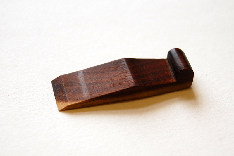
Close up view of wedge

I’ve used a variety of hardwoods: box, cherry, elder, hornbeam and beech and made a variety of shapes and sizes for different tasks. The longer plane lying on its side in the foreground is for shaping violin cornerblocks, for example, while most of the others are for the final stages of arching the top and bottom. Some of these have flat soles for planing flat or convex surfaces; others are gently rounded both across and along the sole and are used for refining concave areas of the arching.

The design is extremely simple as from the photographs of this little plane, made of elder, show: just a body, a wedge and a blade. It’s quite possible to make a plane like this from a solid block of wood simply by chiseling out the required shape. But I’ve found that it’s easier and quicker to adapt the method James Krenov describes in his book ‘The Fine Art of Cabinetmaking’ for making much larger planes. Essentially, the idea is that you saw two slices off the block to make the sides of the plane, shape the bed and throat from the middle section, and then glue it back together.

Here’s an attempt at step by step instructions.

1. Find a suitable blade, around 0.5 inch inches in width and 2 to 2.5 inches long. It’s possible to make one out of an old chisel blade. Another idea is to use a blade that once was part of the set that accompanied a combination or plough plane (these sometimes turn up in second hand tool shops having parted company from the original tool). Or you can buy a new blade from a supplier of Ibex or Herdim violin planes.

2. Now you need a small block of wood, preferably sawn on the quarter. Box, holly, elder, hornbeam, fruit woods and beech are all good. Plane all sides accurately square, though you need not worry about the endgrain faces (diagram, step 1). Then saw it into a sandwich (diagram, step 2) making sure that the layer in the middle (the filling of the sandwich, as it were) is a little wider than the blade you have chosen. Plane the sawn surfaces, keeping them square so that you will later be able to glue the sandwich back together without visible glue lines. The final width of the filling of the sandwich needs to be just a whisker greater than the blade.

Diagram of steps in making a finger plane

3. Saw the central section (the sandwich filling) across at 45° and 85° to make the mouth and throat of the plane (diagram, step 3). Keep the wedge-shaped waste piece because it will be useful later. File the 45° surface smooth, flat and square.

4. Glue the sandwich back together, adjusting the distance between the two filling pieces to give a tight mouth (diagram, step 4). Clamp up and allow plenty of time for the glue to cure.

5. Clean up.

6. Try the blade in position. You will probably need to plane something off the sole so that the mouth is just wide enough for the blade to peep out. Bear in mind that if the sole of the plane is going to be curved, the width of the mouth will initially be wider at the sides of the blade and you’ll eventually need to adjust the mouth to an even width by enlarging it centrally. So keep it on the tight side for now.

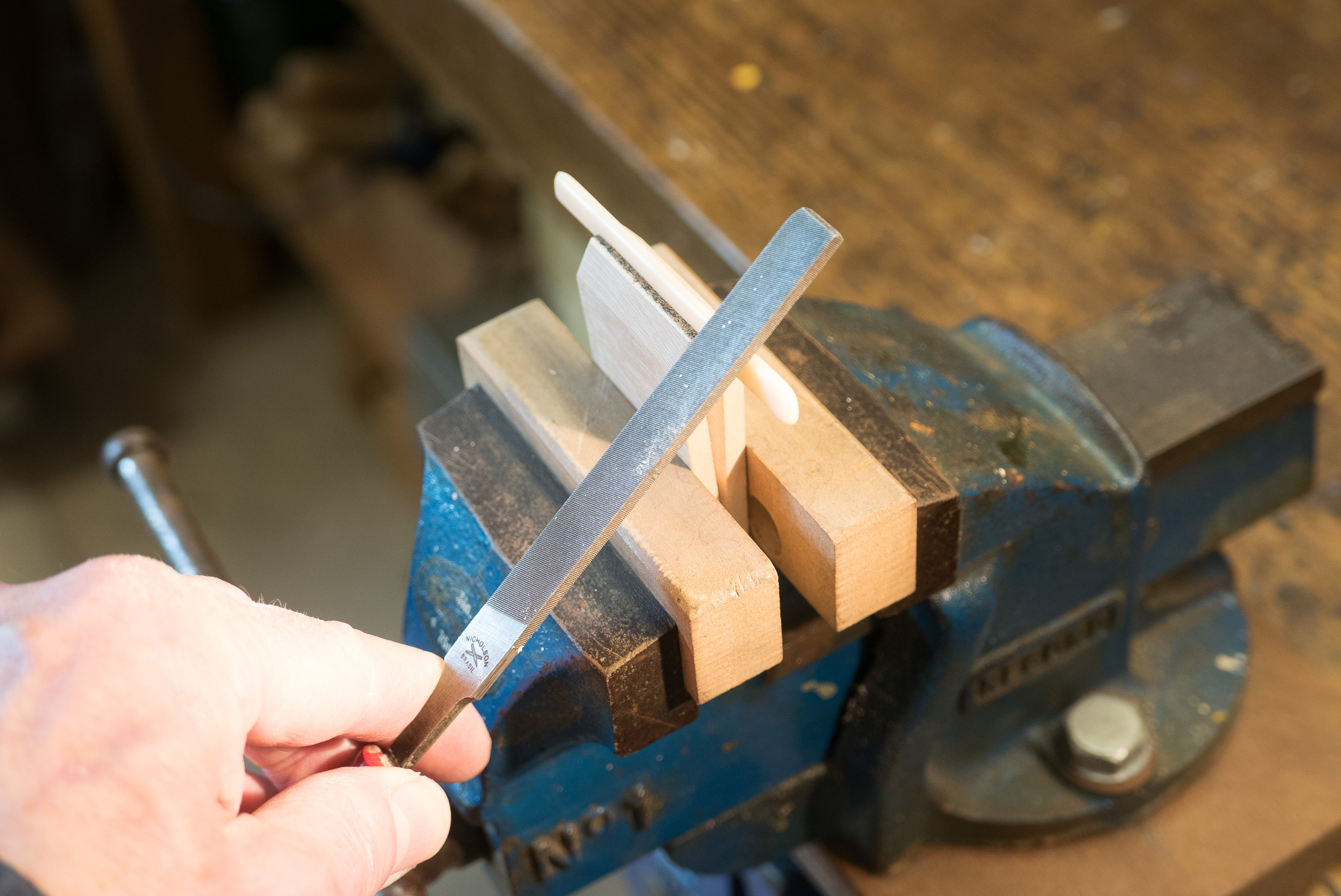
7. Plane or file the sole to the desired profile. This is most easily done by holding a block plane upside down in the vice and moving the workpiece (ie the plane you’re making) over it in the same way that a cooper’s plane is used, though on a much smaller scale – see photograph.

Using a block plane in a vice

Jig for holding wedge

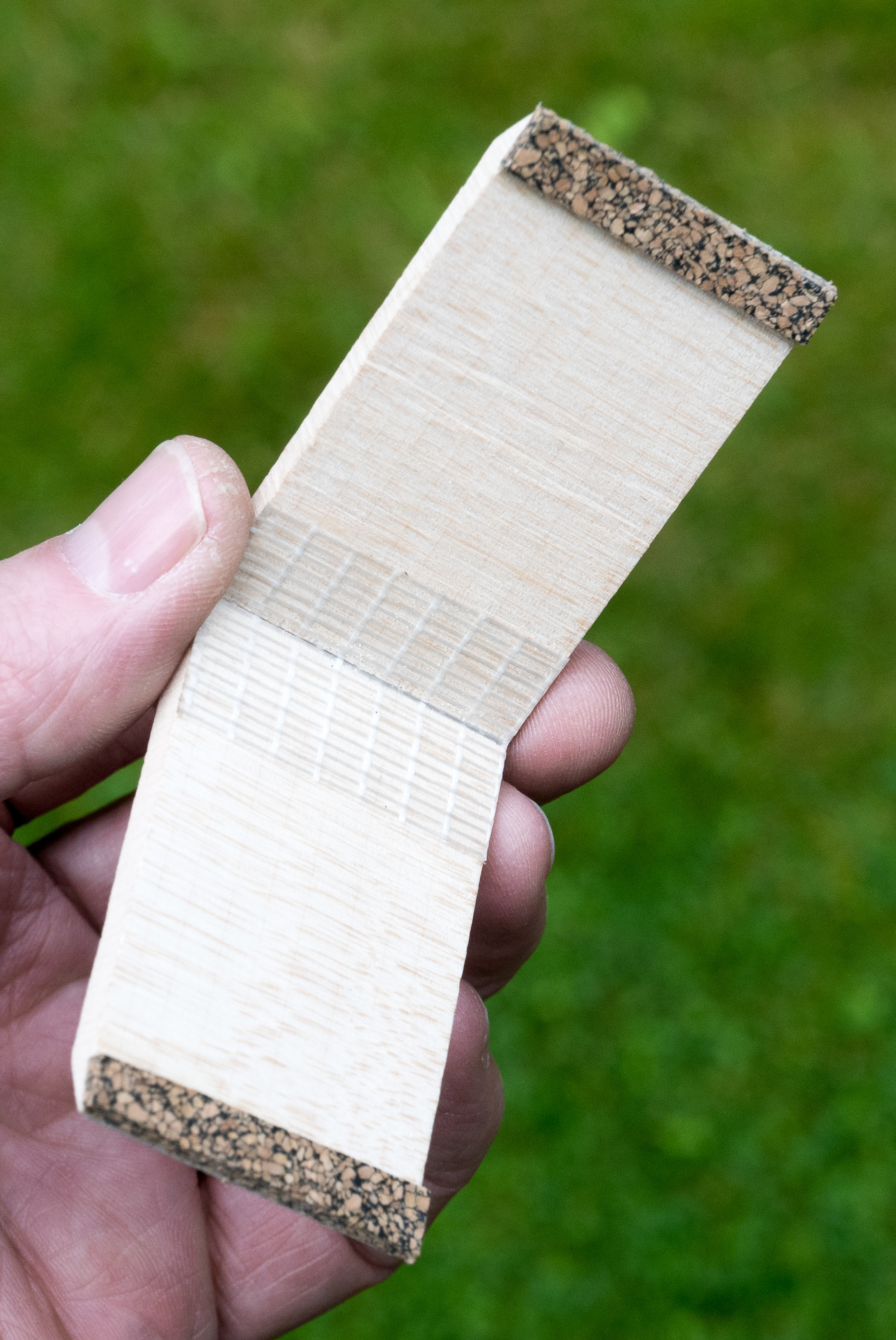
Jig for holding wedge while planing

8. Rough out a wedge. A simple jig like the one in the photograph makes it easier. I like to use a wood of contrasting colour and, if possible, to include a streak of sapwood. But that, of course, is just a whim and of no functional importance. Make the wedge overlength to give leeway for later fitting and leave any fancy carving of the thick end until after the fit is perfected.

9. Put the wedge and blade into position and estimate where to drill for the crossbar that will hold them in place (diagram, step 5). The position isn’t critical but, if the bar is placed too low, it may tend to obstruct shavings as they emerge into the throat. I’ve found that placing the bar about half way up the finished plane works well. Measure the combined thickness of the blade and wedge at this point. Then use a mitre gauge to draw a line on the outside of the place corresponding to the position of the bed. Scribe a second parallel line in front of it (ie towards the toe of the plane). The distance between the two lines should correspond to the combined thickness of the blade and wedge. Draw a third parallel line 1.75 mm further forward again. This is to take account of the 3.5 mm diameter of the cross pin. Half way along this line is the point to drill. While it’s good to get this point placed as accurately as possible, don’t worry too much because you’ll be able to accommodate any inaccuracy by adjusting the wedge.

10. Drill a 3.5mm diameter hole centred on the position that you’ve just marked using a drill press. Before drilling, fit the waste piece that you’ve saved tightly into the gap between the sides of the plane. This will minimise breakout.

11. Turn a short length of hardwood to a diameter of 3.5 mm. Or make it using a dowel plate. Glue into position and trim it off when the glue is dry.

12. Using a coping saw, saw out the curve of the top of the plane. Refine the curve with a knife or file.

13. Then there’s rather a lot of fiddling about to do. Thin the sides of the plane. Adjust the length. Curve the ends. Fit the wedge. File or plane the final profile of the sole and then adjust the curve of the blade and the throat of the plane until you’ve got a tool that does exactly what you want it to do.

14. Obviously, the dimensions, bed angle and other details of the plane can be altered to suit your own requirements.

I’ve no doubt that there are many better, faster, easier and more ingenious ways of making finger planes than this. If you know of them or invent them, please let me know. In a later post, I’ll try to give a bit more detail and discuss modifications and refinements. (See here.)

The Maidstone violin that I wrote about in my last post has found a new home. A young violinist friend, who has grown out of the half-size instrument that I made for him a few years ago, came around to see it at the weekend and liked it enough to take away to try it out properly. If the speed with which he adapted to the new string length, and the good sound that he got out of it, are anything to go by, it will suit him well until he needs a full-size instrument. It’s rather pleasing to think that this abandoned fiddle may have a second lease of life making music again. Here’s the violinist, trying it out in my workshop.

A couple of years ago, I was given a three-quarter size violin in an old wooden case. It was in a shabby state and evidently hadn’t been played for many years. Nor had it ever been a valuable instrument: the scroll and pegbox were crudely carved, the fingerboard and nut were made out of dyed wood rather than ebony and although it had laid in purfling, the job had clearly been done by someone with more concern for speed than accuracy.

There was no label inside but a small brass plate on the wooden case gave a strong clue about its provenance. This was a Maidstone violin, probably made in Bohemia at the end of the 19th century and imported by John G Murdoch and Co in large numbers to provide cheap instruments for schools and for a contemporary movement that sought to bring music to the people by providing group instruction for adults. (See here for more information about this enterprise.)

Although restoring this violin made little sense financially, I thought it would be worthwhile – partly for the opportunity to practice repairing skills on an instrument of little value and partly for the pleasure of returning something that had fallen into a decrepit state back to its former glory. So I took off the fingerboard and substituted a decent piece of ebony, cut out and replaced some wormy wood at the bottom of the pegbox, rebushed the pegholes and fitted new pegs, renewed the edges where they had been damaged and gave it a new bridge, a new soundpost and a new tailpiece. It was an interesting exercise and a rewarding one too, because, when set up with Dominant strings it made a very nice sound indeed.

French polish isn’t the most hard-wearing finish for a guitar and it’s time consuming to apply. But it does have at least three enormous advantages. The first is that, in spite of the repetitive nature of the process, it’s remarkably enjoyable to do. The second is that you don’t need any kit: no spraygun, no mask, no nasty solvents – just a pad and a bottle of shellac. And the third is the fact that, if it does get damaged, it’s fairly easy to repair.

A cedar top classical guitar that I made a year or so ago got damaged the other day when it was treated like a Stratocaster. A young friend of its owner, keen to show off his skills as a rock musician, strummed it using a pick. Unfortunately, he didn’t notice the marks he was making on the soundboard until there was a comet’s tail of scratches on the treble side below the soundhole.

After unstringing the guitar, I steamed out the deeper gashes where the pick had dented the fibres of the wood and then re-polished the top. It’s not quite as good as new because, if you get the light right and look closely, you can just make a out a faint ghost of the original scratch. I’m not quite sure why but perhaps, where the pick reached the surface of the wood, it exposed slightly lighter coloured wood beneath.

I stupidly neglected to photograph the instrument before I started work, but here it is re-finished, re-strung and enjoying the spring sun while the polish hardens off.

%d bloggers like this: