Skip navigation

Category Archives: techniques

Most vices won’t let you file a nut or saddle to shape. Their jaws are too wide and get in the way. Stew Mac make a special vice with tall narrow jaws to get around the problem. I haven’t tried it but I should think that it works fine.  However, it’s quite unnecessary. A simple pair of wooden jaws does the job perfectly well.


The jaws in the photographs below were intended as a prototype. I was planning to make a pair of jaws out of gauge plate or aluminium sheet and wanted to check that I’d got the size about right and that the idea was feasible. It turned out that the wooden version worked so well that I didn’t need to bother.


As I hope can be seen in the photographs, the device is little more than a couple of pieces of maple about 5mm thick, hinged together at their lower ends with glass fibre reinforced tape.


The soprano ukulele that I made from scraps of wood too nice to throw away (but too small for anything else) turned out to be a nice sounding and surprisingly loud instrument. I thought it would be fun to make another.

The classic wood for ukes is Koa, a tree in the Acacia family, which grows only in the Hawaiian archipelago, although it’s closely related to Australian Blackwood (Acacia melanoxylon) and the wonderfully named – after its smell when sawn – Raspberry Jam wood (Acacia acuminata). I was pretty sure that I remembered having a set of Koa somewhere in my stash of guitar wood and eventually I found it.

After a bit of thought, I reckoned that there would be enough material for two ukuleles – one soprano and one tenor. However, as soon as I began to clean it up with a view to book-matching fronts and backs, I ran into trouble. The Koa had a beautiful and dramatic figure, but it was very difficult to plane without causing tear out. That’s often true of highly figured woods of course, but this this was much worse than usual.

A drum sander would have solved the problem – except that I don’t have one. So I tackled it in the old fashioned way.

First I used this large scraper plane to produce a good surface on the face side of each piece before gluing them up, book-matched, for fronts and backs.


DSC_7944

DSC_7933


Now, working from the other side, I needed to get them down to a thickness of under 2mm. Fortunately, the wood had been well sawn and was only around 3mm thick so there wasn’t too much material to remove. This Krenov-type plane with a short thick blade set at an angle of 55° performed better than a plane with the usual 45° blade angle. There was still some tear out, but it did allow me to approach the final thickness without too much anxiety.

The plane was made by David Barron and it’s nicely designed with a soft rounded shape that’s comfortable to hold. It has a sole of lignum vitae and a fairly tight mouth.


DSC_7953

DSC_7956


For the really difficult patches, where the grain was running all over the place, I switched to a toothing plane. This one is a lovely old tool made by Varvill and Son, York, well over 100 years ago. It bears name stamps of two previous owners but it’s in such good condition that I suspect that more of its life has been spent in a tool chest than on the bench. It’s really intended for preparing a surface before laying veneer and, although it’s able to flatten the wildest grain without tearing it, it removes wood very slowly.


DSC_7961

DSC_7963


To speed things up in the less wild areas, I used an ordinary No 4 bench plane fitted with a modified blade. I’ve written about this blade before, so I won’t repeat myself except to explain that the rationale behind it is that the individual serrations are too small to grab and tear out large chunks of wayward grain while, at the same time, being wide enough to remove material fairly quickly – certainly a lot faster than the wooden toothing plane.


DSC_7939

DSC_7936


Having got close to the final thickness with this pair of toothing planes,  I finished the surface with a small Lie Nielsen scraper plane and an ordinary cabinet scraper.


DSC_7946

DSC_7947


Here’s a line up of the workhorses that I put to use.


DSC_7950


And here are fronts, backs and ribs ready to assemble.


DSC_7966


Among the treasure trove of information and tips and tricks at Frank Ford’s website Frets.com there’s a description of how to turn a single-edge razor blade into a miniature cabinet scraper for repairs of guitar finishes. Click here to read it.
 

DSC_7599


I thought that this was a really clever idea and immediately ordered a box of blades to try it out. Ford says that he draws the edge of the blade across a round piece of hard steel such as a screwdriver shank to create a fine hook just as one might finish a full size cabinet scraper.

I’m not sure why, but I couldn’t make it work. Maybe it was my technique or perhaps the steel of the blade had hardened during the sharpening process but despite repeated trials all I could produce was a ragged edge that scraped less well than a blade straight from the box.


The solution was first to grind off the bevelled edge of the blade;


DSC_7600


then to make the blade edge straight and square on a diamond stone;


DSC_7603


and finally to turn a hook with a burnisher in the usual way.


DSC_7606


These little scrapers work extremely well if you need to remove polish or varnish and they’re easy to re-sharpen.


DSC_7598

Most woodworking vices are designed to hold pieces of wood with sides that are parallel. This is a problem for instrument makers because much of the wood they work with is curved or tapered.

So guitar makers frequently use a carvers’ vice, which has adjustable jaws, to get around the difficulty.  Dan Erlewine uses one in his excellent series of videos, Trade Secrets.  And here’s one in my own workshop.
 

DSC_7398


But they’re big, heavy, ugly things (mine is a particularly repellent shade of green) and whenever possible I prefer the simpler solution of a moving accessory vice jaw. This is no more than a block of wood with one gently curved side that allows it to rotate to accommodate the work piece. The flat side is lined with cork and there’s a thin sheet of plywood is glued to the top to maintain it in position while the vice is tightened.


DSC_7379

DSC_7380

DSC_7381

DSC_7382

DSC_7397


I’ve written about these before (see here) so I’ll only say that they’re easy to make and that they’re very effective in gripping gently tapering (10° or less) objects.


The device below  is a little more complicated in having 2 jaws connected at the bottom with a flexible hinge made of leather. It was originally intended to hold the head of a violin or cello  bow while the mortise for the hair was being cut – an invention of Andrew Bellis, who is a bow-maker in Bournemouth.

The 2 jaws are slightly thicker at one end (hence the arrow on the top) which gives it a head start when it comes to accommodating a tapered shape. The flexibility of the hinge allows it to adapt to objects with complex curves. It’s easy to make, too.


DSC_7391

DSC_7393


DSC_7394


Here’s a similar idea but in a more elaborate form. I took the jaws off a small Record vice and substituted cork-lined wood. On one side there’s a permanent version of the moving jaw described earlier. A thin metal bar located by a 3mm rod keeps it in position. I’m hoping the photographs will make things clear.


DSC_7383

DSC_7384

DSC_7403


A couple of photographs of it in action. In the first it’s holding the neck of the soprano ukulele that I mentioned in a previous post. The second shows it gripping the head of a violin bow while it is being re-haired.


DSC_7387

DSC_7390


I’m pleased with how these vice jaws turned out. And it’s certainly convenient having them immediately available to hold an awkwardly shaped work piece. However, I have to say that they’re significantly more effort to make than the simple devices described earlier. Unless you’re dealing with tapers and curves a lot, it may not be worth the time and trouble.

Stanley made two side rebate planes, numbered 98 and 99, which were mirror images of each other, designed to cut either the left or right vertical sides of a channel or dado. I found one in a secondhand tool a long time ago, and then spent years looking for its opposite number.

DSC_6971

While searching, I came across other designs of side rebate planes some of which ingeniously incorporated the ability to cut on left and right sides in a single tool. They’re attractive little devices and I struggled to resist buying them.

DSC_6972

DSC_6973

However, side rebate planes have two defects. The first is that the blades are hard to sharpen. It’s crucially important to maintain the exact angle of the cutting edge relative to the long axis of the blade because there’s no capacity for adjustment in the plane itself. Get it wrong and the blade cuts only the top or bottom.

The second defect is rather more serious: even sharpened and set up properly, they’re useless. I mean that literally: it’s not that these planes don’t work but that problems they could solve or jobs they could make easier never seem to crop up.

At least that’s what I thought until a couple of weeks ago when I found that a truss rod that I was installing into a guitar neck was a whisker too fat to enter the groove that I had routed. I could have got the router out again, but a side rebate plane provided a quicker and easier solution. A few passes and the truss rod was a nice snug fit.

DSC_6968

DSC_6969

Of course, I’ve been writing about my own experience. Other woodworkers may find side rebate planes so handy that they like keep a pair on the back of the bench. If so, I hope they’ll comment and describe the tasks they use them for.

Pattern makers often used long gouges and chisels with a crank between the blade and the handle. This allowed them to operate the tool deep into a workpiece without the handle catching on the edge. In his Dictionary of Tools, R. A. Salaman calls them trowel-shanked, but one often hears them referred to as cranked or crank-handled too.


trowel shank gouge


I’ve got a couple of long in-cannel gouges which I suspect were originally straight and later modified to achieve the same end. Perhaps R. Myers (the name stamped on the handle of the gouge) needed a tool with a cranked shank in a hurry, didn’t have time to obtain one, and so decided to make the best of what he had. The steel at the bent part of the shank is dark and discoloured, which supports the idea because it would surely have been necessary to heat the shank to bend it successfully.

DSC_6959

DSC_6960

Mr Myer’s talent for improvisation and economy prompted me to try something similar with a small chisel blade. I’d often thought that a small crank-handled chisel would be the perfect tool for cleaning up squeezed out glue when putting braces and harmonic bars on guitar soundboards but the only ones that I had come across were too big for what I had in mind, and too expensive as well.

I removed the handle from the chisel, wrapped the blade in a wet rag to prevent the important part of the tool losing its temper and then, after heating the shank to red heat with a propane torch, bent it up about 15°.

When it had cooled, I put the handle back on and was delighted to find that it worked just about as well as I hoped it would. The flat underside of the blade acts as a jig and prevents it digging in, and the raised handle allows it to be used in places where accessibility is restricted.

DSC_6966

DSC_6964

I had intended my previous post to be the last on the V joint. But, as I’ve just completed a guitar using the one that I made for the photographs, the series can end in a rather more satisfactory way by showing how it turned out on an actual instrument.


Here’s a close-up to show any sceptics that the small extra piece of wood glued on to the male part of the V really is invisible in the finished joint – scroll down to the last couple of photographs in this post if you can’t remember what I’m talking about.


Before gluing up the joint, it’s worth taking some trouble to make sure that the two parts fit perfectly. I put the neck in a vise and hold the headstock in place while checking for gaps with a 0.05mm feeler gauge. A bright light behind the joint also helps to reveal places where the fit is defective.

Here I’ve discovered that the sides of the V are a bit loose…

…while the shoulders are tight.

A couple of fine shavings taken off the shoulders of the headstock using a shooting board…

…improves the fit. As a final check, I rub chalk over the male part of the V joint, locate the female part in position and press the joint together hard.

Where the fit is perfect, chalk will be transferred evenly. High spots, on the other hand, show up as a blotch of chalk surrounded by unchalked wood. Here it looks as if there’s a high point on one side near the mouth of the V.

A small file takes off the bump…

…and a second chalk fitting shows that the joint fits pretty well all over, except for a small low spot on one side at the apex of the V. I decide that I can live with that.

The next step is to dust off the chalk, size all mating surfaces of the joint with hot dilute hide glue and leave them to dry.

This is the clamping arrangement that I use. It’s important that the compression force runs through the centre line of the headstock and bears directly on the shoulders of the joint. Chiselling off the front of the V where it projects through the headstock allows the bar of the clamp to sit close to the surface of the headstock.

Once I’m happy that I can get the clamp into exactly the right position, I un-clamp, brush medium strength hide glue onto all joint surfaces, re-clamp it and leave it undisturbed for a couple of hours.

Here it is after taking the clamp off. The shadow below the right hand shoulder of the joint indicates that the headstock is slightly twisted relative to the neck. I suspected that this would happen while I was making the final adjustments but decided that the inaccuracy would be small enough to plane it out after the joint was glued up.

And I’m pleased to say that it was.

The back of the joint looks a bit weird until the extra block is shaved off.

But these two necks show that it comes out all right in the end. Even with a magnifying glass it’s scarcely possible to see that extra wood has been added and after the final shaping it will be quite invisible.

That’s the last of the series of posts on making a V joint. Thanks to anyone who has followed the story this far. Before finishing, I ought to add that there are many variations in the way this joint can be cut. Some makers, for example, prefer to use a template for marking out rather than a ruler and dividers. Please add a comment if you know how to do it quicker or better.

Click on the thumbnails below for larger pictures.

Moving on from my previous post about marking out a V joint, it’s time to cut and trim it to shape.

First, I saw out the V in the headstock, keeping close to the lines but being careful not to saw past them. I try to be brave in sawing up to the line at the narrow end of the V because that’s the hardest part to clean up later.

Next, I stop to put a fresh edge on the chisel that I’m going to use. When it will slice through tissue paper, I reckon that it’s sharp enough.

I clean up the V, paring from both sides towards the middle. Final cuts are carried out with the chisel resting in the knife line that marked out the joint. A small square is useful to check that the sides of the V are flat. The most difficult part of the joint is the apex of the V but a slicing cut with the corner of the chisel will remove the last bit of waste.

Here’s the female part of the V joint in the headstock finished. It shouldn’t be necessary to touch it again.

Now I cut the male part of the joint on the neck, starting with the angled shoulders. I chisel out a ramp for the saw in the usual way…

… and then saw down to the V, keeping clear of the lines.

I mark the starting point of the cuts for the sides of the V on the endgrain…

… place the neck in a vise, tilting it so that the cut will be vertical, and …

saw off the sides of the V with a tenon saw.

I mark and keep the pieces that I’ve just sawn off. They’ll be useful later.

Now I clean up the V and its shoulders with a chisel, paring in from both sides as I did for the headstock.

Here it is almost finished.

The neck and headstock are now tested for fit. Below is the view from the fingerboard side of the neck.

And here’s the view from the back of the neck.

As you can see, there’s a problem at the apex of the V, where a shadow shows that the neck isn’t quite deep enough to fill up the whole of the female part of the joint in the headstock. (My stock of mahogany for necks is planed up at a thickness of 25mm which means that I always run into this difficulty.)

The solution is to add a little extra depth at the apex of the V. This is where the offcuts that I saved come in handy. I prepare a small piece from one of these…

and glue it on, taking care that the direction of the grain in the extra piece is orientated in the same way as the grain of the neck.

When the glue is fully hard…

… it’s sawn roughly to shape…

… and trimmed with a chisel. This addition will be invisible in the completed joint.

The last step is to make sure that everything fits to perfection before glueing up. I’ll discuss how to do that in the next post.

Click on any of the thumbnails below for larger pictures.

Although the geometry of the V joint is simple, it’s surprisingly hard to to visualise if you’ve only seen the joint on a finished guitar. So, in an attempt to make the marking out easier to understand, I’ve sketched it below.

As with all joints, the more precisely it’s marked out the better the final result. It’s crucial that the stock is sized and squared up accurately. The headstock needs to be 17 or 18mm thick to give a final thickness of 19 or 20mm after application of the veneer. The neck must be rather thicker – at least 24 or 25mm – or there won’t be enough wood at the apex of the male part of the V where it engages with the female cut out part in the headstock. The side view in the drawings of the joint above will show what I’m getting at. (Even 25mm thickness may not be enough for full engagement but I’ll show how I deal with that problem in my next post.)

It’s also important that the end grain edge at the lower end of the headstock is exactly square to the sides and faces. I ensure this with a low angle plane and a shooting board.

To begin the marking out, I scribe a centre line down both faces of the headstock with a marking gauge, being careful to scribe both faces from the same edge.

Then I mark the corners of the V with dividers, placing points 18mm either side of the centre line to form the base of the V, and a single point 42mm up from the base on the centreline to define the apex. In the photograph, the pinpoints are marked with chalk to make them more visible.

A single bevel marking knife is used to mark the sides of the V, keeping the ruler on the outside of the V. I try not to cut beyond the point of the V, particularly on the back of the headstock. It doesn’t matter so much on the front which will be covered with veneer later.

To ensure that the ruler doesn’t slip, it’s helpful to fix a strip of fine sandpaper to its underside with double-sided tape.

Here’s the V marked out on one face of the headstock. This process needs to be repeated on the other face so that both sides of the headstock are marked. I haven’t bothered to illustrate this.

Now it’s time to mark out the male part of the joint on the neck. Again, I start by scribing a centre line down both faces. Then I square a line across the upper face of the neck slightly more than 38mm from the end.

Using a sliding bevel set for the angle that I want the headstock to make with the neck (10º in this case, so the bevel is set to 80º) I scribe both sides of the neck from the line that I’ve just squared across it.

Then I square across the back of the neck at the point where the angled lines on the sides end. Finally, I mark out the V on both faces using dividers set to exactly the same dimensions that I used on the headstock. The only difference is that, when it comes to scribing the lines with the knife, I keep the ruler on the inside of the V.

Here’s the top of the neck marked out…

…and here’s the back. You can see that, on the back, the V is positioned slightly further down the neck than it is on the front.

In the next post, I’ll show how I cut out the joint.

You can see larger versions of the photographs by clicking on the thumbnails below.

There are two ways to create the angle between the headstock and the upper end of the neck of a guitar. One is to saw it out whole from a large piece of wood; the other is to make it out of two pieces using a glued joint – either the V shaped joint invented by the early guitar makers or a scarf joint. Of these options, the most rational is the scarf joint. It’s quicker and easier to execute than a V joint and wastes less wood than sawing out a neck and headstock whole. What’s more, it has a large glued surface so it doesn’t rely on nanometric accuracy for its strength.

Despite the obvious advantages of a scarf joint, the V joint has become something of a fetish among guitar makers. This is easy to defend where historical accuracy is concerned. After all, if you’re attempting a copy of a 19th century guitar, it’s desirable – even obligatory – to imitate the constructional methods of the original maker. But for a modern instrument, why prefer a weaker joint that takes longer to make?

The answer, I guess, is to show that you can. It’s not a million miles away from the Georgian cabinet makers who made the pins of their dovetails so skinny that they almost vanished at the narrow end, as you can see in this photograph of the drawer of the table at which I’m sitting as I write this post.

There’s no practical advantage either in strength or speed of production in cutting dovetails like this. Indeed, the reverse must be true. But they do provide an understated way by which makers can demonstrate that they care about seldom seen details and show off their skill.

I’ve found myself using a V joint for both these reasons. Here’s a copy of a 19th century guitar that I’ve mentioned in previous posts. The V joint in this instrument was present in the original and it seemed right to keep it.

On the other hand, the V joint in the guitar below could perfectly well have been a scarf joint. The guitarist for whom I made the instrument didn’t notice it until I drew it to her attention. Still, I enjoyed making it and, for reasons that I can’t properly explain, felt that it was worth the extra time and trouble.

I’ve just cut a couple more V joints for guitars that I’ve got planned for 2012 and, although instructions for making this joint already exist (see here, for example), I thought it might be useful if I kept a camera handy to document the process. In the next post, I’ll explain how I mark out the joint.

Although I was sure that I’d read somewhere that there was a way of using a mirror to help judge when a drill bit was truly vertically, I struggled to find an account of how it was actually done. Eventually, after a lot of googling, I came across this letter and illustration published in Popular Mechanics nearly 80 years ago.

To find out if it worked, I bought a cheap handbag mirror.

First I cut off the hinge and trimmed back the plastic mount along one edge.

Placed next to the drill bit, the mirror showed when the drill was vertical…

… and when it wasn’t.

It’s a simple idea but I was impressed by how well it worked. A problem though, is that the mirror only tells you whether the drill is vertical in one axis. You have to move the mirror around the drill to check whether it’s vertical in the other axis and while you’re doing this, it’s easy to lose the vertical on the first axis.

One solution might be to have an L-shaped mirror or, perhaps better still, a mirror with a hole in its centre. Then, all you’d have to do to check that the drill was truly vertical in both axes would be to move your head.

So I ground a small hole in the centre of the other mirror and tried it out.

This is the view when the drill is vertical.

And when it’s miles off.

Of course, you don’t need a mirror to see when the drill is as far out as that. The benefit is that it makes it easy to spot small deviations from vertical.

Does it work in practice? As a test, I drilled ten 2mm diameter holes at 10mm intervals along a line in a piece of MDF and stuck cocktail sticks into them.

Not perfect – but not bad either. Certainly better than I was able to do in a repeat of the experiment when I used a small try square instead of the mirror as a guide, as you can see below.

Obviously, the best way to drill a truly vertical hole is to use a drill press. But there are occasions when this is impossible because the work piece is too large or too awkwardly shaped. It’s then that this trick with mirrors might come in handy.

As you’ll have gathered from my last post, I’ve been making a steel string guitar recently. That’s something I hadn’t done for a long time, and it got me thinking about truss rods. One puzzle is how they got their name. Doesn’t the word truss conjure up something like the Forth bridge or the roof structure of this magnificent medieval tithe barn¹?

Wikipedia says that, used in an engineering context, a truss is a structure comprising one or more triangular units constructed with straight members whose ends are connected at joints referred to as nodes. So it’s surely an exaggeration to call a rod in the neck of a guitar a truss. Still, it’s not seriously misleading and I expect that most readers will think I’m quibbling.

Another puzzle surrounds the purpose they serve. As far as I know, no classical guitar maker finds them necessary. So why is it that steel string guitar makers never build a guitar without one? The straightforward answer is that steel strings exert more tension when tuned up to pitch than nylon strings and that a truss rod is necessary to counteract this extra force.

But I wondered if this explanation really held water. Using information provided by d’Addario, a reasonable estimate of the combined tension of 6 nylon guitar strings is about 40 kgs, while 6 steel strings exert nearly double that at 70kg. A load of 70 kgs certainly sounds a lot – the weight of an adult man – but don’t forget that it’s acting at a mechanical disadvantage when it comes to bending or breaking the neck of a guitar. The pull is only a few degrees away from parallel to the neck’s longitudinal axis and the compressive forces will be substantially greater than the bending forces.

Using simple beam theory, I made some rough calculations to get a sense of how much the string tension of a steel string guitar would bend the neck. These calculations didn’t attempt to take the taper of the neck into account – I simply pretended that the dimensions of the neck at the first fret remained constant all the way along the neck until it joined the body of the guitar – and they ignored the fact that the fingerboard and the neck are of different woods that have different material properties. (More details of the calculation are given at the end of this post in a footnote, if anyone is interested enough to check².)

The answer turned out to be that, tuned up to pitch, string tension would deflect the nut end of the neck about 1.6 mm forwards of its unloaded position. Although this is bound to be an over-estimate (because the calculation neglected the stiffening effect of the fingerboard and the increasing dimensions of the neck as it descends), I was surprised how large the deflection was. And I wondered if I’d got something seriously wrong. To check, I made a primitive model of a guitar neck to make some actual measurements. As you can see in the photographs below, the experimental neck is smaller in cross section than a real neck but it’s modelled realistically with an angled headstock and nut. Loaded with a 14lb weight, I measured a deflection of 1.47 mm at the nut, which compared fairly well with a theoretical value of 1.26mm derived using the dimensions of the model neck. So I’m moderately confident that my calculations for a real guitar neck aren’t too far out.

It looks as if the obvious answer is at least partly right. You almost certainly do need a truss rod to counteract the bending effect of string tension on the neck of a steel string guitar.

I suspect there’s another reason for truss rods too, and that is to prevent creep. Wood that bears a constant load for a long period tends to deform gradually even when the load is far short of its breaking strain. This is the reason why the ridges of old roofs tend to sag in the middle. In his book, Structures, J E Gordon explains that it’s also the reason why the Ancient Greeks took the wheels off their chariots at night. The wheels were lightly built with only 4 spokes and a thin wooden rim. If left standing still for too long, the wheels became elliptical in shape.

So perhaps I’ve ended up proving something that most guitar makers knew already. However, I don’t feel that the exercise has been a complete waste of time. Musical instruments shouldn’t contain anything that isn’t either necessary or beautiful. Since truss rods certainly don’t fit into the latter category, it’s good to know that they qualify for the former.

Footnotes

1. Thanks to Kirsty Hall for the image of the tithe barn.

2. Details of calculation of neck deflection.

Neck: width = 44mm; depth = 21.5mm; length (to 14th fret) = 355mm
Force exerted by string tension = 700 N
Nut taken as being 8mm above centroid of neck
To work out the area moment of inertia, I assumed that the neck was semi-elliptical in cross section and that the neutral axis ran through the centroid.
Modulus of elasticity of the neck was taken as 10,000 MPa.
Deflection was calculated as Ml²/2EI, where M = moment exerted by strings at the nut, l = length of neck to neck/body join, E = modulus of elasticity of material of neck (taken as 10,000 Mpa) and I = area moment of inertia of neck (assumed to be a half ellipse).

Experienced guitar makers (and books about guitar making) always advise quarter-sawn spruce and vertical orientation of the growth rings for braces and harmonic bars. You hear the same if you ask a violin maker about selecting wood for the bass bar. They’ll explain that wood is stiffest in that orientation, which means that your soundboard will get maximum support for minimum weight.

That might seem the end of the matter but, if you’re one of those disagreeable people who can’t resist probing further and ask if they have ever measured the stiffness of wood in different grain orientations or, if they haven’t, how they can be so sure, you may hear the sound of feet shuffling and detect a swift change of subject.

In fact, as Liutiaio Mottala points out on his interesting website, considering the number of wooden structures that have been built over the years, the information available about how grain orientation influences the physical properties of strength and stiffness is remarkable sparse. In Chapter 4 of The Mechanical Properties of Wood, in USDA Forest Service, Wood Handbook – Wood as an Engineering Material, (available here) there’s a short section on the subject starting on page 4-31, saying that properties of wood do vary slightly according to orientation of annual rings in some species. Disappointingly, it gives no information either about the size of the variation or about which species exhibit the variation. Mottola’s website mentions work done by David Hurd, who found no difference in stiffness between quartersawn and flatsawn wood for the samples he examined but, as far as I can discover, no details are available on line.

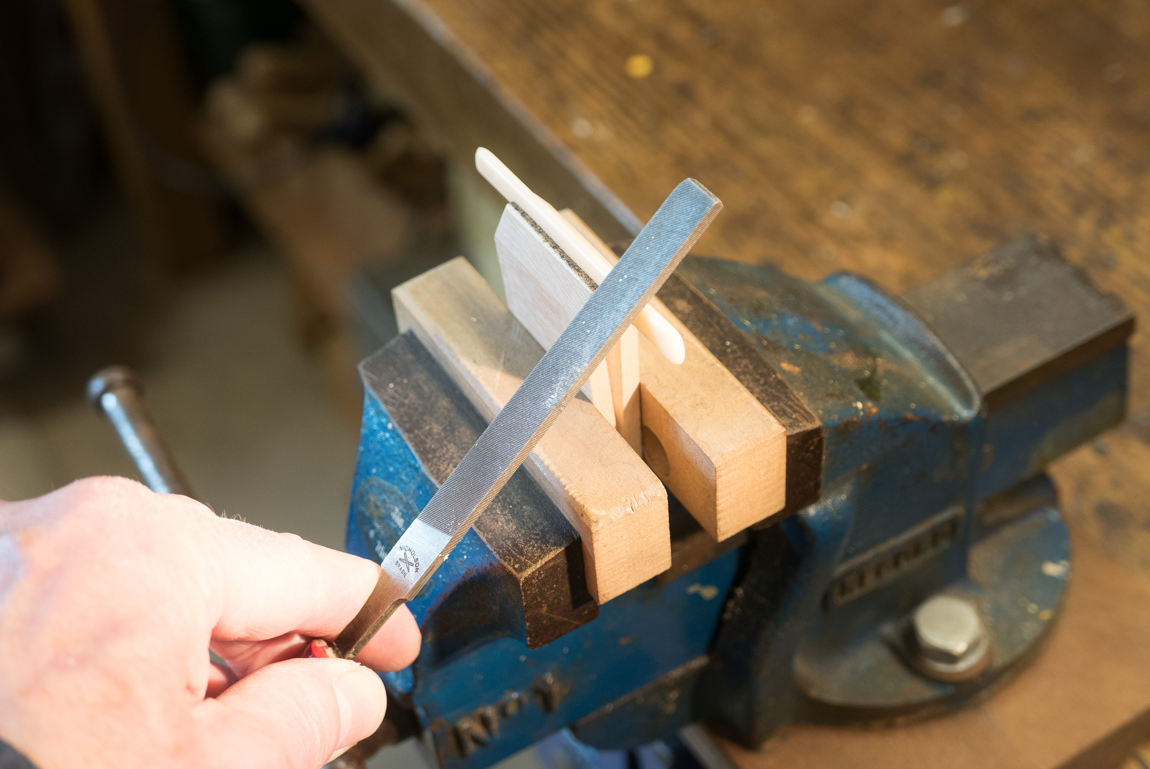
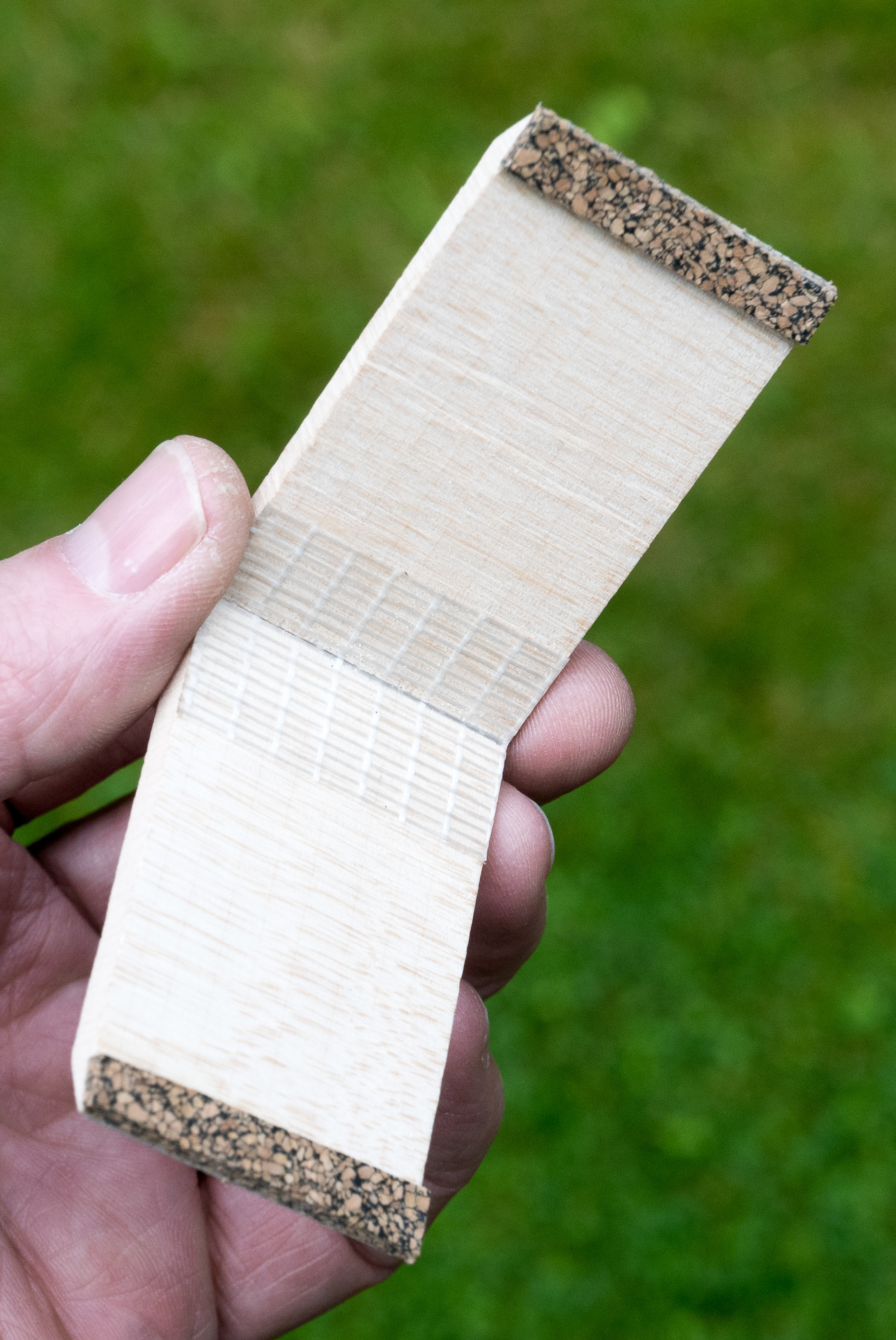
Using the rather primitive set-up shown below, I attempted some measurements myself. The wood is straight grained European spruce with around 14 growth rings to the inch. I sawed and planed 9 pieces, each around 35cms in length and between 7 and 8.5mm in width and depth. I used a shooting board to to make sure that each piece was as straight and as square in section as possible and that the growth rings were oriented more or less parallel to one face (and therefore more or less at right angles to the adjacent face).

Each bar was then clamped in a vice with about 22cms protruding horizontally. I then hung a weight of 2lbs, exactly 20cms away from the vice jaws and measured the resulting downward deflection 4 times for each piece, rotating it through 90° between each measurement.

I’ve summarised the measurements that I made in the table below. The deflections I’ve given are the mean of the 2 measurements for each bar in each orientation. As you can see, the way the growth rings were orientated made remarkably little difference to the magnitude of the measured deflection and there was no consistent tendency for the wood to be stiffer in either of the two orientations.

Now, I’m well aware of the many deficiencies in my experimental design. One of the most serious is that all my specimen bars were cut from the same board and it’s possible that other wood from other trees behaves differently. And of course both the way I prepared my specimen bars and the simple test rig meant that all sorts of errors could have influenced individual measurements. However, the consistency of the findings encouraged me to think that these errors can’t have been very large. If they had been, the size of the difference between quarter sawn and flat sawn deflections would have shown much more variation between different bars.

As a check that the sorts of results I was getting were plausible, I used simple beam theory (max deflection = Wl³ ⁄ 3EI )to calculate the size of deflection that might have been expected, using a value of 10 000 MPa for E, the elastic modulus of spruce. This worked out at 0.34 inches, which was close enough to the deflections that I was observing to reassure me that my simple set-up wasn’t completely inadequate for its purpose.

So what do I conclude? Well, probably nothing that would stand up in a court of law. But I’ve satisfied myself that that spruce cut on the quarter isn’t very different in stiffness from spruce that has been flat-sawn and that where wood of the size and sort used for bracing soundboards is concerned, it doesn’t matter much whether the growth rings are orientated vertically or horizontally. In future, when selecting wood for struts and braces I shall feel free to use either orientation, to make the best use of what I’ve got available.

As a postscript, I was interested to learn from Stewart Pollens’ book Stradivari (ISBN-13: 978-0521873048) that the Hill collection of 50 bass bars taken from violins and cellos of the first rank, including those attributed to Antonio Stradivari himself, contains 11 that are flat sawn (that is to say, the annual rings are orientated horizontally). Maybe instrument makers in 17th century Cremona made less of a fetish about the orientation of growth rings than we do today.

When working on the top of a guitar, I put the instrument on a carpet covered bench and prop up the neck on a block of wood that has a shallow, foam-lined curve cut into the top – as you can see in the photograph above. But I’ve recently learnt a better method. The device below, made out of 2 semi-circles of 18mm plywood, radius about 3 inches, adjusts itself automatically to the taper of the neck and supports it in a far more stable way.

The danger when using the simple block is that it tips over if the instrument is moved along its longitudinal axis. Of course, one can always clamp the block, but with the new neck cradle there’s no need. I’m grateful to Richard Nice (who invented the plane that I wrote about in my last post) for this bright idea.