Skip navigation

Tag Archives: jig

Stewart-MacDonald has been sending me emails recently about a device which allows guitar makers to adjust the height of a guitar nut or saddle while keeping the underside both square and straight (item # 4047 in the StewMac catalogue). Here’s a picture.

I thought that this was rather a good idea.  Although it’s not especially difficult to adjust a nut or a saddle by hand with a file, it’s a tedious job and often takes a while. And the reviews on the StewMac website were positive, saying how quick and accurate the device was.

The drawback is that it’s quite expensive.  By the time I’d paid  shipping and import duty, buying one would probably cost around  $200.   So, I decided to make one for myself.

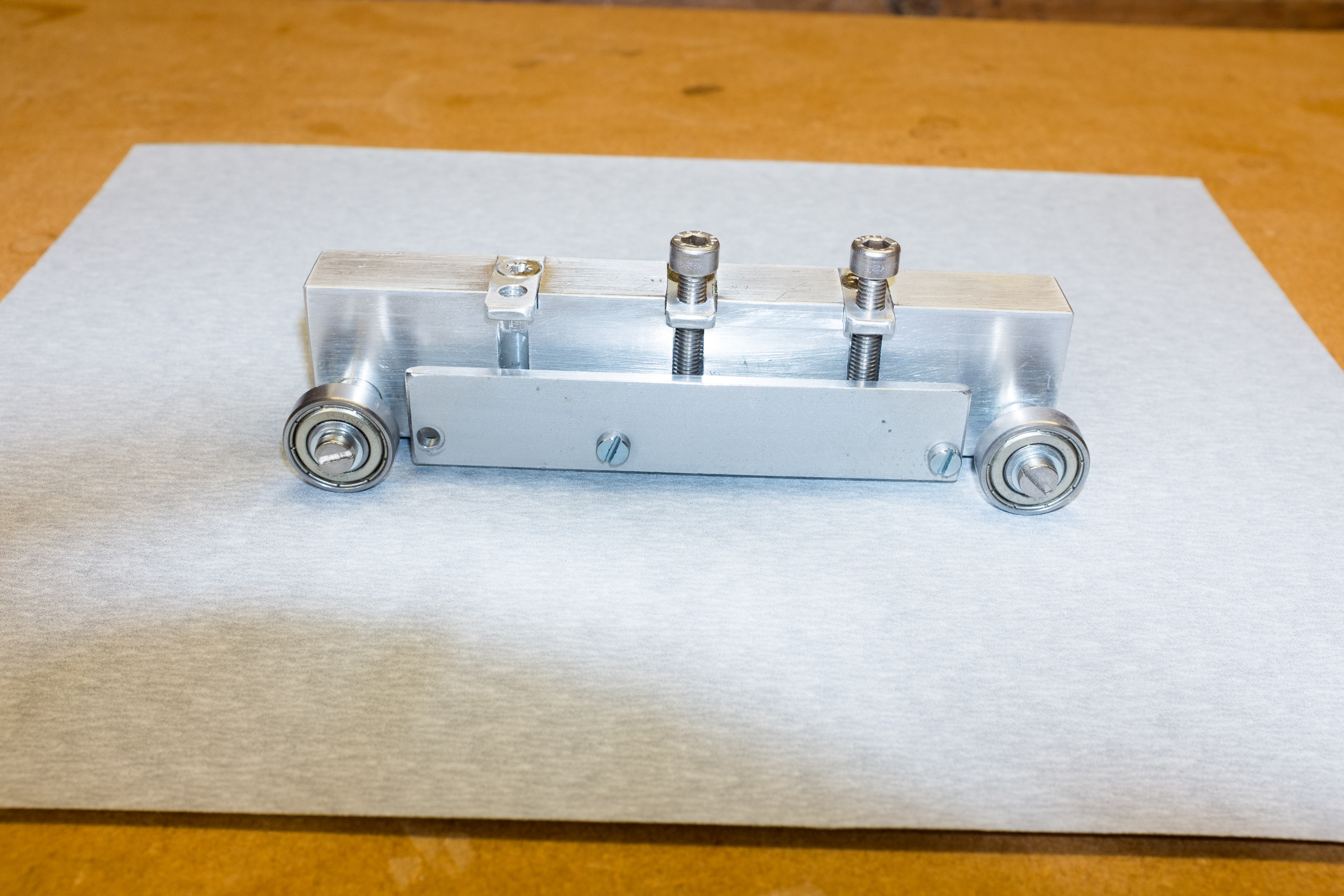
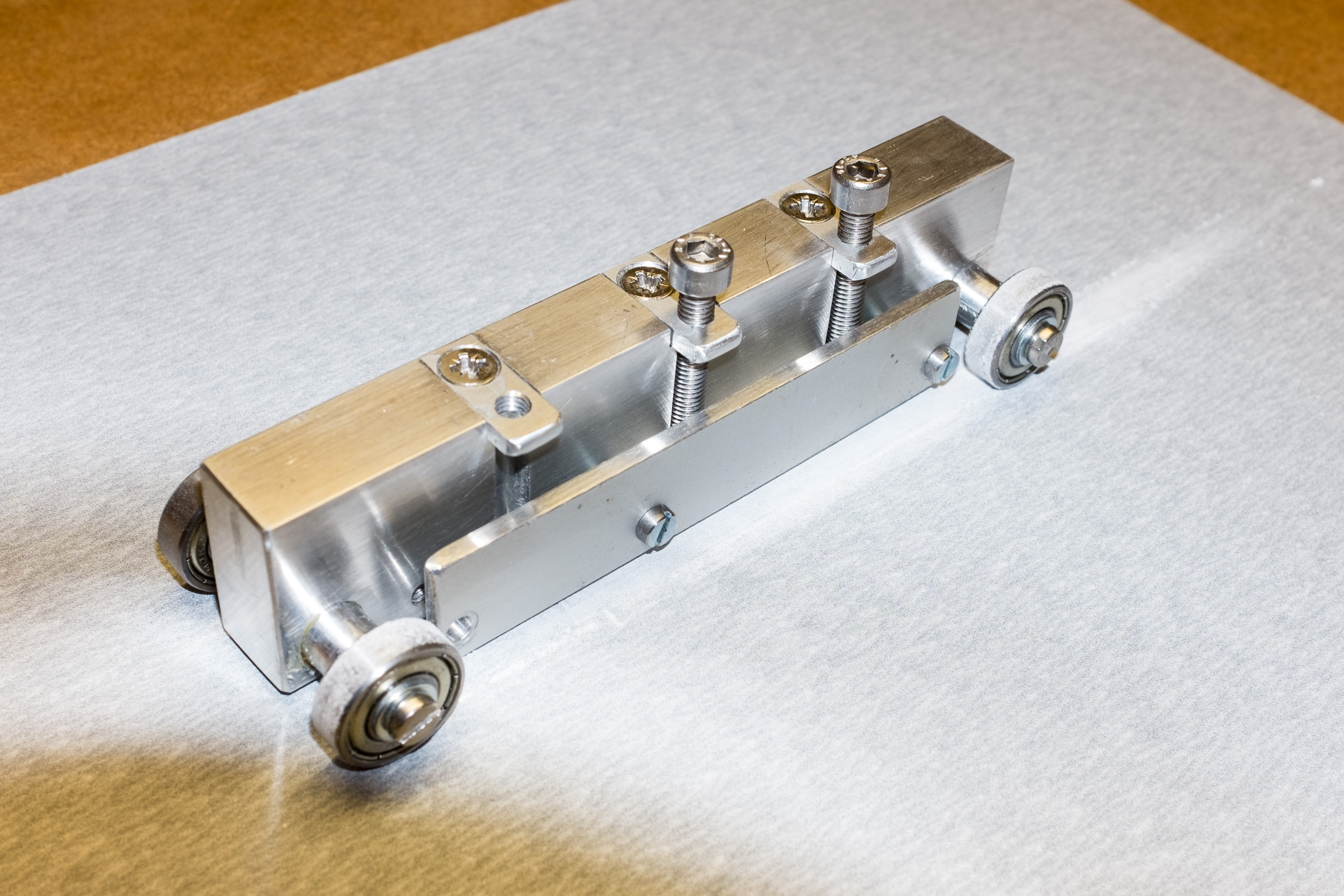
The body is a length of aluminium bar, 15mm x 30mm, drilled at each end to take an axle that carries miniature ball bearings.

Used with a sheet of P280 sandpaper on a flat surface, it worked quickly and accurately.

As I hope you will be able to see from the photographs, it’s not difficult to make, although you will need access to a drill press and a small lathe. The materials needed (aluminium bar and four miniature ball bearings) are easily available and cheap.

Mine took a bit longer to construct than it should have done because I drilled the holes for the axles too low, which meant that the body of the device ended up too far above the sanding surface. So I had to bush the holes and re-drill. If you’re making one, I’d recommend positioning the axle to give a gap of no more than 2mm between the bottom of the device and the sanding surface.

Advertisement

Most woodworking vices are designed to hold pieces of wood with sides that are parallel. This is a problem for instrument makers because much of the wood they work with is curved or tapered.

So guitar makers frequently use a carvers’ vice, which has adjustable jaws, to get around the difficulty.  Dan Erlewine uses one in his excellent series of videos, Trade Secrets.  And here’s one in my own workshop.
 

DSC_7398


But they’re big, heavy, ugly things (mine is a particularly repellent shade of green) and whenever possible I prefer the simpler solution of a moving accessory vice jaw. This is no more than a block of wood with one gently curved side that allows it to rotate to accommodate the work piece. The flat side is lined with cork and there’s a thin sheet of plywood is glued to the top to maintain it in position while the vice is tightened.


DSC_7379

DSC_7380

DSC_7381

DSC_7382

DSC_7397


I’ve written about these before (see here) so I’ll only say that they’re easy to make and that they’re very effective in gripping gently tapering (10° or less) objects.


The device below  is a little more complicated in having 2 jaws connected at the bottom with a flexible hinge made of leather. It was originally intended to hold the head of a violin or cello  bow while the mortise for the hair was being cut – an invention of Andrew Bellis, who is a bow-maker in Bournemouth.

The 2 jaws are slightly thicker at one end (hence the arrow on the top) which gives it a head start when it comes to accommodating a tapered shape. The flexibility of the hinge allows it to adapt to objects with complex curves. It’s easy to make, too.


DSC_7391

DSC_7393


DSC_7394


Here’s a similar idea but in a more elaborate form. I took the jaws off a small Record vice and substituted cork-lined wood. On one side there’s a permanent version of the moving jaw described earlier. A thin metal bar located by a 3mm rod keeps it in position. I’m hoping the photographs will make things clear.


DSC_7383

DSC_7384

DSC_7403


A couple of photographs of it in action. In the first it’s holding the neck of the soprano ukulele that I mentioned in a previous post. The second shows it gripping the head of a violin bow while it is being re-haired.


DSC_7387

DSC_7390


I’m pleased with how these vice jaws turned out. And it’s certainly convenient having them immediately available to hold an awkwardly shaped work piece. However, I have to say that they’re significantly more effort to make than the simple devices described earlier. Unless you’re dealing with tapers and curves a lot, it may not be worth the time and trouble.

In his book Violin Restoration (ISBN 0-9621861-0-4), Hans Weisshaar has a photograph of a self-adjusting jig that will hold violin bridges while they’re being planed. I was rather taken by the simplicity and ingenuity of the idea and I thought that I’d make one to see if it worked any better than the very basic holder, shown below, that I use at the moment.

The clever part about Weisshaar’s jig is that one side is free to rotate which means that it can adjust itself to fit bridges of different geometry, holding them all equally tightly. It’s easier to show how it works with a few photographs than it is to describe it.

Extra holes allow the swivelling side to be mounted closer to the fixed side to accommodate three-quarter and half size bridges.

A small block glued to the bottom helps to hold the jig against the edge of the bench or in a vice.

Although the device works well, it’s probably not going to be much use anyone except a violin maker. Still, I thought that the idea of using a freely moving arm or jaw to grasp pieces of wood when the sides aren’t parallel had wider applicability. You might be able to use a scaled up version for planing tapers on table legs, for example. And the accessory jaw for holding tapered shapes in a vice that’s shown on the Tools and Jigs page of this site (scroll down to the second item) draws on the same principle.


Larger versions of these photographs are available by clicking on the thumbnails below.

A comment on the previous post asked about setting the honing angle.

Here’s one way of doing it. Set a sliding bevel to the angle you’re after. (I chose 30°.) Then, after fitting the chisel into the mould, adjust the position of the mould in the honing jig, by eye, so that the longitudinal axis of the chisel runs parallel with the blade of the sliding bevel.


I glued a strip of wood across the underside of the mould so that it can be located in the honing jig at the same angle every time. And that’s it.


Eventually, I suppose, repeated honing will shorten the chisel and increase the angle of the secondary bevel. That will mean that it’s time to regrind the primary bevel and repeat this process to restore the angle of the secondary bevel.

A point I forgot to mention in the earlier post is that it’s worth creating a stop in the moulding at its upper end to prevent any tendency for the chisel to slide up while it’s being honed. Here you can see a stop formed by the lip that mirrors the indentation between the socket and the handle of the chisel.


A pair of chisels reground with left and right skewed edges is almost essential for cleaning out the sockets of lap dovetails. These chisels are useful for other tasks as well – tidying up the inside of the pegbox of a violin or cello, for example. I’ve got several pairs in different sizes and, although I don’t use them everyday, there are jobs where no other tool will do.

Actually, that isn’t quite true. A fishtail chisel makes a good substitute and, because it can work into both left and right pointing corners, you only need one tool rather than a pair. Last Summer, visiting Mark Bennett in his workshop in Yorkshire (see below) I saw him using one made by Lie-Nielsen. It was such an attractive looking tool that, even though I didn’t really need it, I couldn’t resist buying one to try.

After it arrived, I honed it, maintaining the 25° angle of the original grind. Perhaps it was my lack of skill – keeping such a small bevel flat on the stone wasn’t easy – but I never managed to get it properly sharp. What’s more, the edge that I did achieve didn’t stand up to use on hardwoods.

Of course, there’s an obvious solution to both these problems: create a secondary bevel at a slightly steeper angle. Indeed, Lie-Nielsen recommend exactly that in the leaflet that comes with the chisel.

However, I was reluctant to do this freehand because, although I was sure that it would work well enough the first few times, I knew that in the long run I’d be unable to maintain the same angle. This would mean that I’d end up with a rounded secondary bevel that would require more and more honing with each sharpening to get a decent edge. And, quite apart from the extra time this would take, it’s a bad idea to hone or grind a fishtail more than absolutely necessary. There isn’t much metal there in the first place and with each grinding the cutting edge gets progressive narrower. 

A honing jig would have solved the problem, except for the fact that I couldn’t make  the conical shape of the shaft of the tool  fit securely into any of the jigs in my workshop.

In the end, I got around this difficulty by casting a mould out of the sort of two-part wood filler that sets hard in about 30 minutes. I’ve written about this technique for holding awkwardly shaped object before (scroll down in the Tools and Jigs section of the website) so I won’t go into it in detail here. But briefly, you mix a generous quantity of the filler, spread it on a board (in this case a thin piece of wood of a size that would fit into an Eclipse honing jig), cover with a layer of cling film, and press the object you want to mould into it, holding it place with a weight or a clamp until the filler sets. Then, of course, you can take it out and get rid of the cling film.

I’m hoping that the photographs below will the idea clear:

And it worked – at least for one of the objectives. The edge on the chisel was keen enough to slice soft paper towel and to pare endgrain.

Whether it will achieve the second objective of minimising attrition of the blade with repeated sharpenings is another matter. Time will tell.

A couple of years ago, I wrote about a simple device that made it easy to plane a taper on small pieces of wood – something that’s hard to do accurately if you try to hold the wood in a vice. (The piece is still available in the Tools and Jigs section of the website.) After I’d posted it, Jeff Peachey, who specialises in the conservation of books, sent me a photograph of a rather similar jig that he had made, which had the advantage of an adjustable endstop. I’ve been meaning to incorporate this modification ever since, but have only now got around to it. Below is a photograph of the original jig with a glued endstop of 1.5mm plywood.

To add a adjustable endstop, I inserted two short lengths of 6mm studding, drilling the pilot holes under size and then tapping the holes before screwing in the studding. Because the studs are inserted into endgrain, I was doubtful if they would hold so I glued them in too. And, to be doubly sure, I cross drilled the studs in situ and popped in a nail shank, the end of which is visible on the side of the jig.

Then I cut slots in a small piece of maple to make the endstop and fixed it in place over the studs with washers and nuts.

Here is the modified jig, ready for action.

A worthwhile improvement, I think. It will be possible to match the height of the endstop to the size of the end of the wedge and, should the endstop get damaged, it will be easy to true it up again.

In the meantime, Jeff Peachey has made a much bigger and better device, which is primarily intended for planing thin boards although it can cope with wedges too. There’s photograph of it on his website here.

When working on the top of a guitar, I put the instrument on a carpet covered bench and prop up the neck on a block of wood that has a shallow, foam-lined curve cut into the top – as you can see in the photograph above. But I’ve recently learnt a better method. The device below, made out of 2 semi-circles of 18mm plywood, radius about 3 inches, adjusts itself automatically to the taper of the neck and supports it in a far more stable way.

The danger when using the simple block is that it tips over if the instrument is moved along its longitudinal axis. Of course, one can always clamp the block, but with the new neck cradle there’s no need. I’m grateful to Richard Nice (who invented the plane that I wrote about in my last post) for this bright idea.

All that remains at this stage is to cut the inner and outer circles to make the annulus of the rosette. I start by drilling a hole in the centre of the work piece…

… and then use a Dremmel mounted in a shop-made jig to cut the circles. (More details of the jig are available in the ‘Tools and Jigs’ section of this site.)

Here are the two rosettes that I’ve talked about in early posts in this series cut out.

And here are a few more. Going clockwise from top left, they’re made of English yew, laburnum, spalted beech, spalted crab apple and mulberry burr.

It’s probably best to leave them attached to their base until you’re ready to install them on the soundboard but, as you can see from the two rosettes at the bottom, I don’t always heed my own advice.

I’ve been making a few small wooden boxes to give as Christmas presents. They don’t really have much practical function, except as a place to keep pencils or stamps or other odds and ends, but they’re fun to make and people seem to like them. Part of the pleasure of constructing them comes from the small scale of the project. It’s a day’s work rather than a month for a guitar or a violin. And they allow you use up scraps of wood that were too nice to burn but that are too small to make much else out of. They also provide an opportunity to show off a bit, which brings me to the reason for writing this post.

Even people who know nothing about woodwork and cabinetry have heard about dovetails and recognise them as an emblem of craftsmanship in wood. So that’s the method of construction you should use if you want your skill to be noticed.

If you’re going to cut dovetails, it’s much easier if you’ve got a proper vice. Because of the position of the screw and slide bars in most bench vices, it’s only possible to grip the edge of the board that you’re dovetailing. A dovetailing vice, on the other hand, grips the whole work piece, preventing it vibrating and aiding accurate sawing. They are especially valuable for wide boards but they’re good for smaller pieces too. The idea came from Robert Wearing’s book, The Resourceful Woodworker, (ISBN 0 7134 8006 8). He uses threaded metal bars to provide the clamping force but I cannibalised the wooden handscrews from an old clamp that I picked up in a second hand tool shop. The vice is simply cramped to the top of the bench when needed.

I left the screws much longer than necessary for any dovetailing so that the vice would open wide enough to accommodate the body of a guitar when working on the tail stripe.

And, should you be wondering how the boxes turned out, here are a few photographs:


This is the second half of the story, started in my last post, about making a rosette from spalted beech.

The next step was to cut the channels around the edge of the rosette to receive the border strips. Again, I used my jig mounted Dremel for this.

DSC_0014
DSC_0015

Here the channels have been cut and the decorative strips bent more or less to the right curvature on the bending iron ready for glueing in.

DSC_0016
DSC_0022

And here is the finished rosette, planed flush with the soundboard and given a wipe of shellac. I shan’t cut the soundhole until I’ve planed the soundboard down to it final thickness.

DSC_0026

A few weeks ago, I bought a block of spalted beech from Mark Bennett and mentioned, in a previous post, that I hoped it would make some striking guitar rosettes. I’ve been trying out some ideas. Here’s the piece of wood that provided the starting point.

DSC_0001

Having decided which face looked most attractive, I set up the bandsaw for a fine cut and sawed two veneers at about 4mm thickness. Then I book-matched them to create a more or less symmetrical pattern, by gluing them onto thin (1/64 inch) plywood for stability. Actually, there’s a bit more to it than that. First, using weak hot hide glue, I stuck a sheet of paper to a 6 by 6 inch square of 6mm MDF. Then I stuck a similar sized square of 1/64 inch thick plywood over that, again using thin hide glue, and weighted it down until the glue was dry. This provided the base onto which the veneers were glued.

DSC_0004

Using a Dremel mounted in a jig (details of jig available here) I cut out the rosette making the depth of cut just through the layer of thin plywood. It was then possible to remove the rosette using a thin blade – an ordinary knife from the dinner table works well – sliding it between the plywood and MDF layers in the plane of cleavage provided by the paper. Any paper or glue remaining on the underside of the rosette can easily be cleaned off with a hot damp cloth, which of course was the reason for using hide glue in the first place.

DSC_0007

I missed the opportunity to photograph either the detached rosette or the routed channel in the soundboard but below you can see the rosette being glued into position on the soundboard, weighted down so that it dries flat.

DSC_0010

%d bloggers like this: