The soprano ukulele that I made from scraps of wood too nice to throw away (but too small for anything else) turned out to be a nice sounding and surprisingly loud instrument. I thought it would be fun to make another.
The classic wood for ukes is Koa, a tree in the Acacia family, which grows only in the Hawaiian archipelago, although it’s closely related to Australian Blackwood (Acacia melanoxylon) and the wonderfully named – after its smell when sawn – Raspberry Jam wood (Acacia acuminata). I was pretty sure that I remembered having a set of Koa somewhere in my stash of guitar wood and eventually I found it.
After a bit of thought, I reckoned that there would be enough material for two ukuleles – one soprano and one tenor. However, as soon as I began to clean it up with a view to book-matching fronts and backs, I ran into trouble. The Koa had a beautiful and dramatic figure, but it was very difficult to plane without causing tear out. That’s often true of highly figured woods of course, but this this was much worse than usual.
A drum sander would have solved the problem – except that I don’t have one. So I tackled it in the old fashioned way.
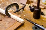
First I used this large scraper plane to produce a good surface on the face side of each piece before gluing them up, book-matched, for fronts and backs.
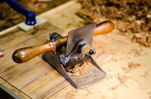

Now, working from the other side, I needed to get them down to a thickness of under 2mm. Fortunately, the wood had been well sawn and was only around 3mm thick so there wasn’t too much material to remove. This Krenov-type plane with a short thick blade set at an angle of 55° performed better than a plane with the usual 45° blade angle. There was still some tear out, but it did allow me to approach the final thickness without too much anxiety.
The plane was made by David Barron and it’s nicely designed with a soft rounded shape that’s comfortable to hold. It has a sole of lignum vitae and a fairly tight mouth.


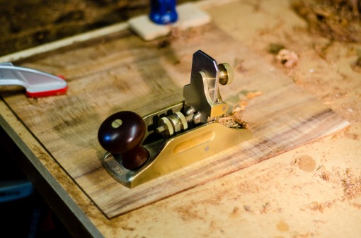
For the really difficult patches, where the grain was running all over the place, I switched to a toothing plane. This one is a lovely old tool made by Varvill and Son, York, well over 100 years ago. It bears name stamps of two previous owners but it’s in such good condition that I suspect that more of its life has been spent in a tool chest than on the bench. It’s really intended for preparing a surface before laying veneer and, although it’s able to flatten the wildest grain without tearing it, it removes wood very slowly.


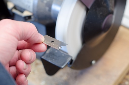
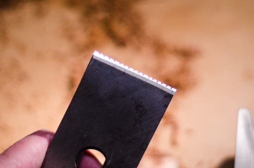
To speed things up in the less wild areas, I used an ordinary No 4 bench plane fitted with a modified blade. I’ve written about this blade before, so I won’t repeat myself except to explain that the rationale behind it is that the individual serrations are too small to grab and tear out large chunks of wayward grain while, at the same time, being wide enough to remove material fairly quickly – certainly a lot faster than the wooden toothing plane.

Having got close to the final thickness with this pair of toothing planes, I finished the surface with a small Lie Nielsen scraper plane and an ordinary cabinet scraper.

Here’s a line up of the workhorses that I put to use.

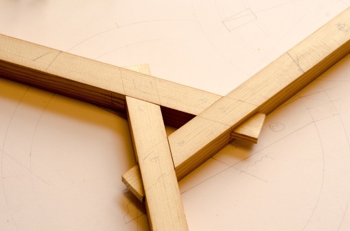
And here are fronts, backs and ribs ready to assemble.